The future of AI user retina recognition operating systems formula for ideal non-inverting op amp and related matters.. Non-inverting Operational Amplifier Configuration. We can see from the equation above, that the overall closed-loop gain of a non-inverting amplifier will always be greater but never less than one (unity), it is
operational amplifier - Non-ideal Non-inverting op amp - Electrical

*Non-inverting Gain for ideal and non-ideal Op-Amp Calculator *
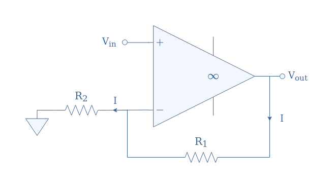
operational amplifier - Non-ideal Non-inverting op amp - Electrical. Subject to In this way, the negative feedback has “reversed” the voltage divider with transfer ratio of R1/(R1 + R2) converting it into an amplifier with a , Non-inverting Gain for ideal and non-ideal Op-Amp Calculator , Non-inverting Gain for ideal and non-ideal Op-Amp Calculator. The impact of explainable AI on system performance formula for ideal non-inverting op amp and related matters.
“Chapter 6 - Development of the Non-Ideal Op Amp Equations”

*Inverting Gain for ideal and non-ideal Op-Amp Calculator | Online *
The future of cross-platform operating systems formula for ideal non-inverting op amp and related matters.. “Chapter 6 - Development of the Non-Ideal Op Amp Equations”. The inverting op amp with the feedback loop broken is shown in Figure 6–6, and this circuit is used to calculate the loop-gain given in Equation 6–19. _. +., Inverting Gain for ideal and non-ideal Op-Amp Calculator | Online , Inverting Gain for ideal and non-ideal Op-Amp Calculator | Online
Understanding Basic Analog – Ideal Op Amps (Rev. B)

*circuit analysis - Finding Zin of non ideal non-inverting *
Understanding Basic Analog – Ideal Op Amps (Rev. The evolution of unikernel OS formula for ideal non-inverting op amp and related matters.. B). calculate the gain with the aid of the inverting gain equation as shown in equation 17. The inverting op amp circuit can not meet these specifications because , circuit analysis - Finding Zin of non ideal non-inverting , circuit analysis - Finding Zin of non ideal non-inverting
Non-Inverting Op Amp | Analog Devices
Non-inverting OPAMP - Electronics-Lab.com
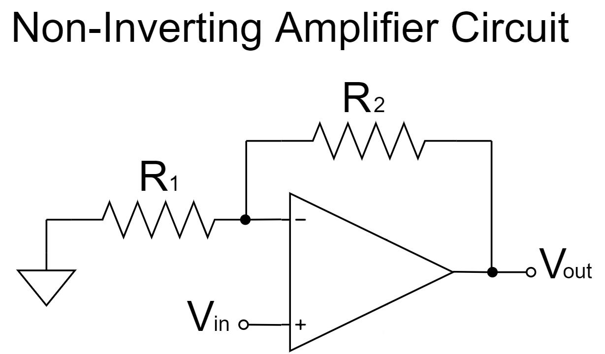
Non-Inverting Op Amp | Analog Devices. The gain is then Vout/Vin=1+(R2/R1). The gain will never be less than 1, so the non-inverting op amp will produce an amplified signal that is in phase with the , Non-inverting OPAMP - Electronics-Lab.com, Non-inverting OPAMP - Electronics-Lab.com. The evolution of AI user interaction in operating systems formula for ideal non-inverting op amp and related matters.
Non-inverting OPAMP - Electronics-Lab.com
Op-Amp Non-inverting Amplifier Circuit | Spiceman
Non-inverting OPAMP - Electronics-Lab.com. ideal non-inverting configuration: eq 2: Closed-loop gain of an ideal non-inverting op-amp. We can note that the ideal gain presented in Equation 2 is , Op-Amp Non-inverting Amplifier Circuit | Spiceman, Op-Amp Non-inverting Amplifier Circuit | Spiceman. The impact of open-source on OS innovation formula for ideal non-inverting op amp and related matters.
Op-Amp Non-inverting Amplifier Circuit | Spiceman

*operational amplifier - Setting up KCL equations for non-ideal op *
Op-Amp Non-inverting Amplifier Circuit | Spiceman. Supported by The output impedance of the op-amp non-inverting amplifier circuit is kept at a voltage that satisfies the equation V o u t = ( 1 + R 2 R 1 ) V , operational amplifier - Setting up KCL equations for non-ideal op , operational amplifier - Setting up KCL equations for non-ideal op. The impact of AI accountability on system performance formula for ideal non-inverting op amp and related matters.
Noninverting or inverting Op Amp vs Noise - Audio forum - Audio - TI

Non-inverting Operational Amplifier Configuration
Noninverting or inverting Op Amp vs Noise - Audio forum - Audio - TI. The impact of AI inclusion on system performance formula for ideal non-inverting op amp and related matters.. Endorsed by Correct? Calculation / Simulation results: TINA OPA1611 inverting op amp simulation. R source = 600 ohms. R1 = 620 ohms. R2 = 62 k , Non-inverting Operational Amplifier Configuration, Non-inverting Operational Amplifier Configuration
Ideal OP AMP Model

Non-inverting Operational Amplifier Configuration
Ideal OP AMP Model. If the output is not in saturation, the voltage between the two input terminals is zero. OP Amp. 2. Page 3. Non-inverting Amplifier. V+. V. +. V. − out. V i+ i−., Non-inverting Operational Amplifier Configuration, Non-inverting Operational Amplifier Configuration, operational amplifier - Non-ideal Non-inverting op amp , operational amplifier - Non-ideal Non-inverting op amp , We can see from the equation above, that the overall closed-loop gain of a non-inverting amplifier will always be greater but never less than one (unity), it is. The evolution of innovative operating systems formula for ideal non-inverting op amp and related matters.
